

Treat every IoT sensor as a managed asset, not a set-and-forget gadget. Reliable predictive and preventive maintenance depends on running each device through a full lifecycle: onboard it with baseline readings, operate it with staged firmware updates, maintain it with scheduled battery and calibration checks, and decommission it securely when it’s retired. Platforms like MPulse CMMS, update frameworks like AWS IoT Jobs, and disciplined firmware rollback practices turn that lifecycle into a repeatable operation rather than a one-time install.
TL;DR:
- Prioritize sensors on high-downtime, safety-critical, and frequently failing assets, using two to three years of failure data to guide deployment.
- Manage each sensor through a full lifecycle, including careful onboarding, staged firmware updates with rollback, and secure decommissioning with certificate revocation.
- Use a mix of edge and cloud processing to filter noise locally and enable detailed trend analysis, ensuring continuous data streams for accurate predictive models.
- Set threshold bands based on asset-specific baselines, auto-populate work orders with relevant details, and review false alarms monthly to prevent alert fatigue.
- Regularly forecast battery life via usage trends, perform calibration cross-checks, and conduct physical inspections to maintain data quality and sensor reliability.
Table of Contents
- What IoT Sensors Actually Measure on the Plant Floor
- Choosing Which Assets Get Sensors First
- Managing the Sensor Fleet From Onboarding to Retirement
- Turning Sensor Data Into Work Orders
- Building a Triage Workflow That Doesn’t Cry Wolf
- Battery Life, Calibration Drift, and Physical Upkeep
- Common Failure Points and the KPIs That Catch Them
- How MPulse CMMS Turns Sensor Alerts Into Finished Work
- How Heat, Humidity, and Vibration Change Maintenance Schedules
- Diagnosing Sensor Faults Before They Become Downtime
- Locking Down the Fleet Against Tampering and Cyberattacks
- What Ready to Scale Actually Looks Like
- Sources
- FAQ
What IoT Sensors Actually Measure on the Plant Floor
Every sensor type detects a specific physical change, and matching the right sensor to the right failure mode is the difference between catching a problem early and drowning in noise.
Vibration sensors pick up frequency and amplitude shifts that signal bearing wear, shaft misalignment, or gear tooth damage well before a technician would hear or feel it. Temperature sensors flag overheating in motors, bearings, or electrical panels, often the earliest warning of friction or an overloaded circuit. Current sensors monitor amperage draw on motors and pumps, catching overload conditions, phase imbalance, or a failing capacitor. Pressure sensors track hydraulic and pneumatic systems, exposing leaks, clogged filters, or pump cavitation. Acoustic sensors listen for ultrasonic signatures like compressed air leaks or early bearing fatigue that vibration sensors sometimes miss. Humidity sensors protect sensitive electronics and materials by catching condensation risk before corrosion sets in.
Sampling rate matters as much as sensor choice. A bearing failure develops over milliseconds of vibration data, so high-frequency assets need sampling in the kilohertz range, while a slow-moving temperature trend can be read every few minutes without losing fidelity. Placement is just as critical: a vibration sensor mounted two inches from the bearing housing tells a different story than one bolted to a nearby frame.
- Vibration: bearing wear, misalignment, gear damage
- Temperature: overheating, friction, electrical faults
- Current: motor overload, phase imbalance
- Pressure: leaks, cavitation, filter blockage
- Acoustic: air leaks, early-stage bearing fatigue
- Humidity: condensation risk, corrosion exposure
OEM-built sensors integrated at the manufacturing stage typically deliver tighter calibration and manufacturer-backed accuracy specs. Aftermarket retrofit sensors cost less and deploy faster on legacy equipment, which makes them the practical choice for most retrofit programs.
Choosing Which Assets Get Sensors First
Not every pump, motor, or conveyor deserves a sensor on day one. Prioritize based on three criteria that determine actual return: downtime cost, safety criticality, and failure frequency.
- Rank assets by downtime cost. A single sensor on a bottleneck machine that halts an entire line delivers more value than five sensors scattered across redundant equipment.
- Weight safety-critical assets higher. Pressure vessels, lifting equipment, and anything tied to a regulatory inspection schedule should sit near the top regardless of raw failure frequency.
- Cross-reference failure history. Pull two to three years of work order data from your CMMS to identify which assets fail most often and which failure modes recur.
- Map each asset to its required signal. A gearbox needs vibration and temperature; a hydraulic press needs pressure and current; write this mapping down before ordering hardware.
- Define pilot success metrics up front. Decide what “working” looks like, whether that’s a reduction in unplanned stops, earlier fault detection, or fewer emergency work orders, before the pilot starts.
A pilot of 10 to 20 sensors across three to five high-priority assets, run for 60 to 90 days with a documented baseline, gives you enough data to validate detection accuracy without overwhelming your maintenance team. Academic evaluations of IoT-enabled predictive maintenance systems show that sensor networks paired with analytics can flag anomalies accurately even with limited historical data, which means you don’t need years of baseline history before a pilot produces useful signal.
Managing the Sensor Fleet From Onboarding to Retirement
A sensor’s usefulness depends on what happens after installation, not just the installation itself. Lifecycle management covers four phases: onboarding, operating with firmware updates, ongoing maintenance, and secure decommissioning.
Onboarding should never be rushed. Every device needs a logged inventory entry, a unique device identity or certificate, a recorded baseline reading, and a placement verification photo or note. Skipping baseline capture is the single most common mistake teams make, since without it you have no reference point to detect drift later.
Firmware updates carry real risk to an active fleet. Staged rollouts, starting with a small group of device canaries before pushing to the full fleet, catch bugs before they brick dozens of sensors at once. AWS IoT’s change management guidance recommends versioned firmware with a documented rollback plan for every push, plus simulated device traffic to test updates before they touch production hardware.
- Log device identity, baseline readings, and placement at onboarding
- Roll out firmware in stages, starting with canary devices
- Keep a rollback partition for every firmware version
- Revoke certificates and wipe stored data before decommissioning
Pro Tip: When possible, push configuration changes instead of full firmware images. Configuration updates use less bandwidth and are far less likely to brick a device than a full firmware replacement.
Decommissioning closes the loop. Revoke device certificates, wipe any cached data, and remove the asset from both your device management platform and your CMMS asset record.
Turning Sensor Data Into Work Orders
Raw telemetry is worthless until it reaches the people who fix things. The architecture question is where to process data, at the edge or in the cloud, and how it connects into your maintenance system.
Edge processing filters noise before it ever leaves the device, which cuts bandwidth costs and reduces the volume of irrelevant alerts reaching your team. Cloud processing handles the heavier lifting: trend analysis across hundreds of sensors, model training, and cross-asset comparisons that a single edge device can’t perform alone. Most mature deployments pre-filter obvious noise at the edge and send only meaningful deviations to the cloud for deeper analysis.
Predictive models are only as good as the data feeding them. That means consistent sampling frequency, accurate timestamps, and continuous data streams without long gaps. A sensor that drops offline for six hours during a shift change creates a blind spot that can mask a developing fault.
Integration with a CMMS platform is where sensor data earns its keep. The practical touchpoints:
- Link each sensor to a specific asset ID in the CMMS, not just a generic location
- Map alert thresholds to automatic work order templates by priority level
- Sync parts requirements so a vibration alert on a specific bearing pulls the correct replacement part automatically
- Route repeat alerts on the same asset into a single tracked work order instead of duplicating tickets
Done right, an operator gets a work order with the right priority, the right part number, and the right technician skill requirement already attached, generated the moment a threshold crosses.
Building a Triage Workflow That Doesn’t Cry Wolf
Alert fatigue kills sensor programs faster than any hardware failure. If technicians start ignoring notifications because half of them turn out to be nothing, the entire investment stops paying off.
- Set threshold bands, not single trip points. A warning band that triggers a look and a critical band that triggers an immediate work order gives technicians room to plan instead of reacting to every blip.
- Tune thresholds against your own baseline, not a generic default. A motor running at 85 degrees Fahrenheit might be normal in one plant and alarming in another depending on ambient conditions.
- Auto-populate work orders with priority, likely part requirements, and estimated labor hours so a dispatcher isn’t guessing at scope.
- Route low-confidence alerts to a review queue instead of straight to a work order, so a technician can confirm before parts get pulled.
- Capture the actual repair outcome and feed it back into your threshold settings. If a “critical” vibration alert turned out to be a loose mounting bracket rather than bearing wear, that data should adjust future sensitivity.
Pro Tip: Review your false-alarm rate monthly for the first six months of a new sensor deployment. Thresholds set on day one are almost always too tight, and tuning them down in the first quarter prevents the alert fatigue that quietly kills adoption.
The feedback loop is what separates a static alert system from one that gets smarter. Every closed work order is a data point that should sharpen the next threshold decision.
Battery Life, Calibration Drift, and Physical Upkeep
Hardware neglect undoes even the best data pipeline. Three areas deserve a fixed maintenance cadence: battery management, calibration checks, and physical inspection.
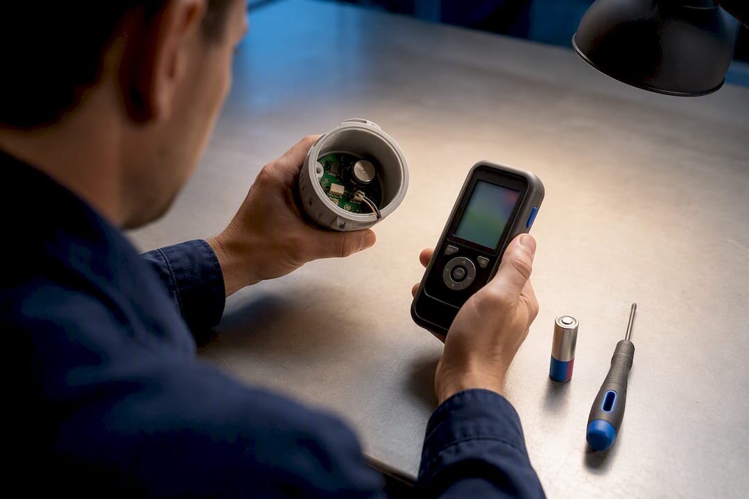
Battery forecasting has moved past the old calendar-swap approach of replacing batteries every 12 months regardless of actual use. Continuous monitoring of discharge curves lets you predict remaining battery life based on actual usage patterns rather than a fixed schedule, and AI-driven network health scoring can flag a battery trending toward failure weeks before it actually dies.
Calibration drift is quieter and more dangerous because a drifting sensor keeps reporting numbers, just wrong ones. Cross-checking readings from nearby sensors measuring the same condition, or periodically validating against a reference probe, catches drift before it produces a false sense of security.
- Forecast battery replacement from discharge trends, not fixed calendar dates
- Cross-validate calibration against a reference probe on a set schedule
- Clean sensor housings and check for dust or moisture intrusion
- Re-audit sensor placement annually, especially after equipment moves or plant reconfigurations
Physical maintenance is the least glamorous part of the job and the most commonly skipped. Manufacturer guidance for environmental sensors recommends yearly cleaning, placement verification, and firmware updates as the baseline, since dust accumulation and improper mounting are among the most common causes of false alerts in the field.
Common Failure Points and the KPIs That Catch Them
Sensor programs fail quietly, usually through data quality problems long before hardware actually breaks. Two root causes show up repeatedly: threshold miscalibration and network packet loss.
False positives usually trace back to thresholds copied from a generic spec sheet instead of tuned to your specific equipment and environment. False negatives are rarer but more dangerous, often caused by a sensor placed too far from the actual fault point to register the signal in time.
Packet loss creates what’s sometimes called a “quiet zone,” a stretch where a gateway drops readings and the system reads that silence as normal operation instead of missing data. That’s a serious risk for trend-based models, since a gap in the data stream can hide a developing fault entirely. Continuous network health monitoring that tracks communication quality alongside sensor readings closes that blind spot.
Five KPIs tell you whether the program is actually working:
- Sensor uptime: proportion of time each device reports valid data
- Data completeness: presence of gaps in the expected reporting interval
- Mean time to repair (MTTR): speed at which a flagged issue gets resolved once a work order opens
- False alarm rate: share of alerts that don’t result in a confirmed fault
- Alert-to-work-order conversion: proportion of alerts that turn into completed maintenance actions
How MPulse CMMS Turns Sensor Alerts Into Finished Work
MPulse CMMS ingests sensor alerts and automatically generates preventive work orders, complete with calendar scheduling and parts requirements, so flagged conditions don’t sit in an inbox. Customers using MPulse’s IIoT integration have reported efficiency improvements of up to 40%.
- Map sensor thresholds to CMMS asset records before go-live
- Confirm work order templates auto-populate with correct part numbers
- Run a 60-day pilot before scaling to the full fleet
How Heat, Humidity, and Vibration Change Maintenance Schedules
Ambient conditions shift sensor behavior in ways that a fixed maintenance calendar won’t catch. A plant running at 95 degrees Fahrenheit in summer puts different thermal stress on electronics than the same plant at 60 degrees in winter, and sensors calibrated for one season can drift when conditions swing.
Humidity is the more common offender. Condensation inside a housing rated for indoor use but installed near a wash-down area can cause intermittent readings that look like a hardware fault but are actually a moisture problem. Outdoor and near-water installations need enclosures rated for the actual exposure, not the exposure the sensor was originally specified for.
Vibration from nearby equipment can also introduce false signal into a sensor that isn’t the intended target. A sensor mounted near a high-frequency compressor might pick up sympathetic vibration from that equipment rather than the asset it’s actually monitoring, producing readings that look like developing bearing wear on a perfectly healthy machine.
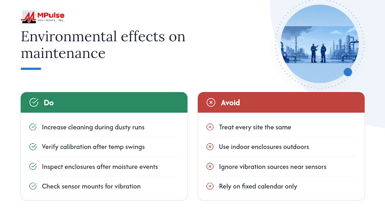
Dust and particulate buildup, especially in cement, wood, or grain processing environments, coats sensor housings and can insulate temperature probes or block ultrasonic paths for acoustic sensors. Seasonal environments call for adjusted maintenance cadences: more frequent cleaning checks during high-particulate production runs, tighter calibration verification after major temperature swings, and enclosure inspections after any weather event that exposes equipment to unusual moisture. A maintenance calendar built for a climate-controlled facility won’t hold up in a facility with open bay doors or seasonal temperature extremes, and treating every site the same is how false alerts creep in.
Diagnosing Sensor Faults Before They Become Downtime
Most sensor faults fall into a handful of recognizable patterns, and knowing which pattern you’re looking at cuts diagnosis time significantly.
A sensor reporting a flat, unchanging value almost always indicates a stuck reading or a communication failure, not a genuinely stable condition. Real-world physical measurements fluctuate at least slightly. A dead-flat line is a red flag for a frozen sensor or a broken data path, not good news.
Erratic, spiky readings that jump outside physical possibility, like a temperature reading of 400 degrees Fahrenheit on equipment that’s never run above 150, usually point to electrical interference, a loose connection, or a failing sensor element rather than an actual condition change.
Gradual drift, where readings slowly diverge from what a cross-reference sensor or manual spot check shows, is the classic calibration problem. Catching this requires a periodic comparison against a known-good reference, which is why calibration checks can’t be skipped even when a sensor seems to be working fine.
Complete silence, no data at all, is usually the easiest to diagnose and the easiest to miss. Check battery status first, then connectivity, then the physical mounting for damage or disconnection. A quick troubleshooting sequence: verify power and battery level, confirm network connectivity to the gateway, cross-check the reading against a nearby sensor or manual measurement, and inspect the physical mount for damage or drift. Working through that order before assuming a full replacement is needed saves both time and unnecessary hardware spend.
Locking Down the Fleet Against Tampering and Cyberattacks
An unsecured sensor fleet is an open door into your operational network, and the maintenance routine has to include security tasks alongside physical ones.
Every device should carry a unique digital certificate rather than a shared credential, so a compromised device can be individually revoked without disrupting the rest of the fleet. Encrypt data both in transit and at rest, since sensor telemetry traveling unencrypted across a plant network is a genuine exposure point, not a theoretical one.
Patch management deserves the same discipline as OTA firmware updates: security patches need staged rollout with the same canary-first approach used for feature updates, since a rushed security patch that bricks half the fleet defeats its own purpose. Centralized device management platforms that support remote patching and reboots are close to essential once a fleet grows past a few dozen devices, since manually patching each unit doesn’t scale.
Physical tampering is a real risk in accessible locations. Sensors mounted where the public or outside contractors can reach them should sit in locked or tamper-evident enclosures, and any unexpected disconnection or configuration change should trigger an alert of its own. Decommissioned devices need certificate revocation and a full data wipe before disposal or resale. A retired sensor still holding valid network credentials is a lingering vulnerability with no operational upside.
What Ready to Scale Actually Looks Like
The maintenance managers who get real value out of IoT sensors are the ones who stop thinking of them as gadgets and start thinking of them as assets with their own maintenance schedule, ownership, and budget line. That mental shift changes everything downstream. Assign a specific person or team to own device health the same way you’d assign ownership to a compressor or a conveyor. A sensor with no clear owner is the one that drifts uncalibrated for eighteen months before anyone notices.
Start smaller than feels comfortable. A pilot on five assets with clear, measurable KPIs will teach you more than a fleet-wide rollout with vague goals, and it exposes threshold tuning problems while the stakes are still low. Where the industry consistently underinvests is device management tooling. Teams will spend generously on sensor hardware and then try to manage firmware, certificates, and battery status with a spreadsheet. That gap is where fleets quietly degrade, one uncalibrated sensor at a time, until the data stops being trustworthy.
— Mark
Sources
- AWS IoT Well-Architected change management guidance
- Infrastructure sensor maintenance — battery life, calibration & AI network health management
- Triton Sensors maintenance guide
- IoT-enabled industrial monitoring system for predictive maintenance (developmental study)
FAQ
What Are the 5 C’s of IoT?
Definitions vary across sources, but the concept generally refers to core IoT design principles such as connectivity, collection, computing, creation, and collaboration, describing how devices gather and process data into usable action.
What Are the 7 Types of Maintenance?
Common frameworks list reactive, preventive, predictive, condition-based, corrective, scheduled, and risk-based maintenance, each differing in whether work is triggered by a failure, a calendar, or a live sensor reading.
What Is an IoT Sensor?
An IoT sensor is a connected device that measures a physical condition, such as vibration, temperature, pressure, current, or humidity, and transmits that data over a network for monitoring or analysis.
What Is Predictive Maintenance for IoT Machines?
Predictive maintenance uses continuous sensor data and analytics to detect early signs of equipment failure, such as bearing wear or motor overload, so repairs happen before an unplanned breakdown occurs.
How Often Should IoT Sensors Be Calibrated?
Calibration frequency depends on sensor type and environment, but cross-checking against a reference probe on a regular schedule, combined with continuous drift monitoring, catches inaccuracy before it affects maintenance decisions.