Failure code analysis is the practice of coding and studying equipment failures so maintenance data can reveal patterns and root causes. Standards such as ISO 14224 and NERC’s GADS guidance point to one rule: record the observable failure mode first, mark any diagnosis as provisional, and update it after verification. A structured CMMS workflow, such as the one in MPulse CMMS, makes that habit easy to repeat.
TL;DR:
- Code the observable mode first, such as leakage or failure to start, and keep any suspected mechanism provisional until evidence confirms it.
- Adapt ISO 14224, IEC 60812, and NERC/GADS rather than copying their libraries; a short taxonomy crews use beats an extensive list they skip.
- For recurring or critical failures, verify the report, identify the mode, diagnose the mechanism, reproduce it if needed, then validate corrective action.
- Capture equipment identity, lost function, mode, provisional mechanism, context, timestamps, exposure, corrective action, and verification status so later analysts can interpret rates.
- Compare failure rates only across a defined asset population, failure definition, exposure measure, and time basis; no universal acceptable rate exists.
Table of Contents
- Why failure modes and failure mechanisms are not the same thing
- Which standards and code libraries should your taxonomy borrow from?
- How does failure analysis validate and refine your codes?
- What fields make a failure-code record analyzable?
- What should crews and analysts do from discovery to closure?
- Why separating observation from diagnosis speeds learning
- Putting the checklist to work in a CMMS
- FAQ
- Sources
Why failure modes and failure mechanisms are not the same thing
A failure mode is how a failure shows up: the observable deviation from required function. A failure mechanism is the physical or chemical process that produced it. ISO guidance on failure modes treats modes such as fail to start, leakage, vibration and overheating as observations or effects, not automatically as diagnoses. The mechanism, why it happened, is a separate assertion that usually needs evidence.
A few pairs show the gap:
- Fail to start is the mode. A seized bearing or a failed contactor could be the mechanism.
- Leakage is the mode. A degraded seal or a corroded fitting could be the cause.
- Overheating is the mode. Blocked airflow or insulation breakdown could be behind it.
- In electronics, a loss of signal is the mode, while wire bond lifting, corrosion or ESD/EOS damage is the mechanism.
Conflating the two does real damage. If a technician codes “bad bearing” for a pump that simply would not start, the record asserts a cause nobody confirmed. That can lead crews to investigate or replace the wrong component, and can make trend charts less meaningful. Exact phrasing at the point of entry helps preserve the distinction between observation and diagnosis.
Which standards and code libraries should your taxonomy borrow from?
You do not need to invent a taxonomy from scratch. Several published sources can help inform a failure-code taxonomy:
- ISO 14224: This reliability-data standard defines data categories and a shared “reliability language,” and recommends long-term planned data collection with a clear equipment taxonomy, failure data, maintenance data and data quality controls.
- IEC 60812 and FMEA: FMEA is a systematic evaluation of how an item or process might fail, the effects of each failure mode and potentially its causes. IEC 60812 frames it as decision support, and its value grows when the analysis is updated as designs, processes and operating conditions change.
- NERC/GADS code lists: These are a large cause and mechanism library. Appendix H lists labels such as alignment, arcing, leaking, vibration, seized and worn.
The practical NERC rule is worth copying directly: code the major component responsible, and keep the triggering sequence in narrative text.
NERC’s coding guidance shows why context beats a deceptively precise dropdown: the same visible event can be coded without losing the trigger that started it.
Adapt these libraries to your equipment rather than adopting them wholesale. A short list your crews actually use beats a long one they skip.
How does failure analysis validate and refine your codes?
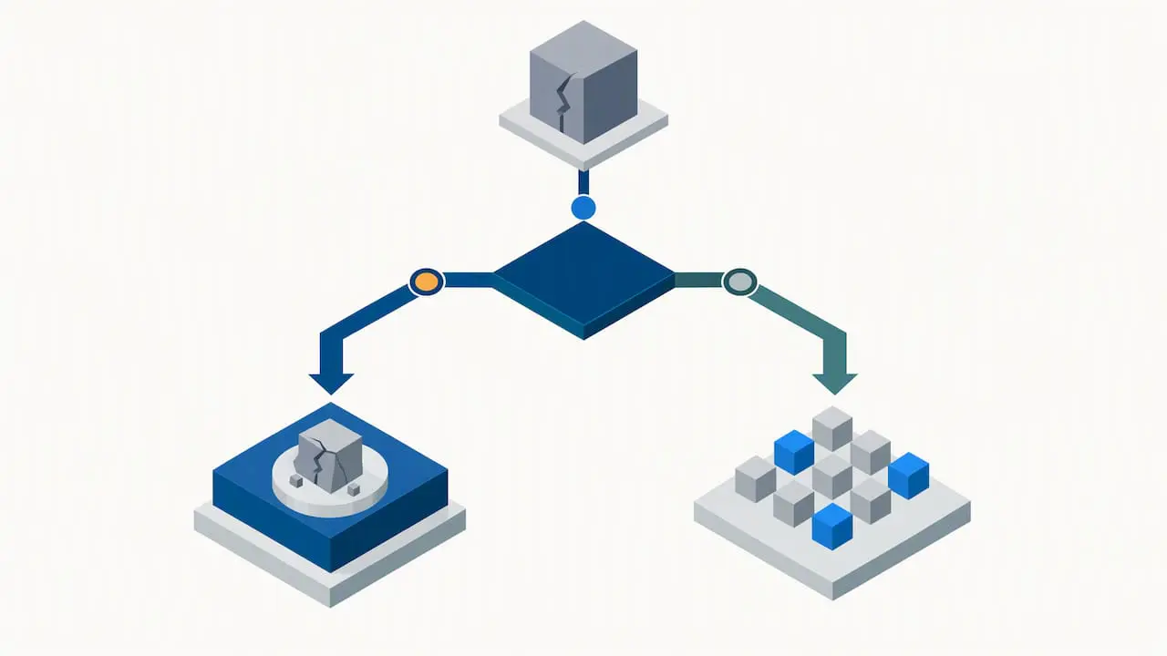
Coding captures what happened. Failure analysis confirms why. The steps, as laid out in NASA’s failure analysis procedures, run in a fixed order:
- Verify that the failure occurred and matches the report.
- Determine the failure mode, meaning the symptoms.
- Diagnose the failure mechanism, meaning the physical cause.
- Reproduce the failure under designed stress conditions, if needed.
- Recommend corrective action and validate that it works.
Verification and diagnosis can inform code updates. After verification, a provisional code can be marked verified. Mechanism diagnosis can inform the cause field. If a reproduction test does not confirm the suspected mechanism, keep the record marked unknown until there is enough evidence.
FMEA and coded history form a loop. Use FMEA prospectively to identify potential failure modes and effects. Use coded work-order history retrospectively to test which modes actually occur and whether corrective actions reduce recurrence. If you want to build the prospective side, our PFMEA overview explains how to structure it.
Not every failure deserves a lab. A procedural guide for microelectronics analysis notes that technique selection, equipment and cost should drive the choice between destructive analysis and non-destructive or sampling approaches.
Pro Tip: Reserve physical failure analysis for recurring or critical failures, and let statistical sampling handle the low-consequence rest.
What fields make a failure-code record analyzable?
A record is analyzable when someone who was not there can understand it later. At minimum, capture:
- Equipment ID and its place in the taxonomy
- The required function that was lost
- The observable failure mode
- The suspected mechanism, flagged as provisional
- A narrative covering the trigger and context
- Start and end timestamps
- An exposure metric: operating hours, cycles or demands
- The corrective action taken
- A verification status
Boundaries and time definitions matter as much as the fields. ISO 14224 covers equipment boundary, taxonomy and timeline issues and treats data collection as a long-term investment that needs multi-year data for confident analysis. Exposure is the reason a failure rate means anything. There is no universal acceptable failure rate; a meaningful one needs a defined population, operating exposure, failure definition and time basis. Our guidance on asset criticality in a CMMS shows how to segment by consequence.
Finally, decide who may set codes. Let technicians enter provisional codes, and let a reliability lead or analyst mark them verified.
What should crews and analysts do from discovery to closure?
Use this sequence on every failure work order:
- Record exactly what was observed, in plain words.
- Enter a provisional code, or “unknown” if the evidence is thin.
- Collect evidence: photos, readings, parts, sensor traces.
- Schedule failure analysis if the failure is recurring or critical.
- Update the code only after verification.
- Log the corrective action and confirm it held.
For the narrative, a short template works: What was running, what changed just before, what was seen, what was done, what remains unconfirmed. Capturing triggers and dependencies in those five lines preserves context that no dropdown can.
Pro Tip: Review every “unknown” code on a fixed cadence, such as monthly, and reconcile the results with your FMEA.
An unknown code with a good narrative and later review is often more valuable than an early unsupported diagnosis, which is why NERC’s mechanism library includes an “Unknown – investigation underway” code. If you want a pilot plan, our post on failure codes for plant teams lays one out.
Why separating observation from diagnosis speeds learning
Most root-cause efforts stall because the data already contains an answer someone guessed on day one. When records separate the observed mode, the cause, and the action taken, it is easier to review the evidence and interpret KPIs. You can see which modes are common before you argue about why.
Operationally, this takes structure, not heroics. Scheduled calendar views keep verification work from slipping, and sensor integrations supply the trace evidence that later analysis depends on. Our advice is to adopt an explicit “unknown” policy and to tie every FMEA update to a reconciliation against coded history. Doing both can help teams learn from their failure records, rather than relying on a bigger code list alone.
— Mark
Putting the checklist to work in a CMMS
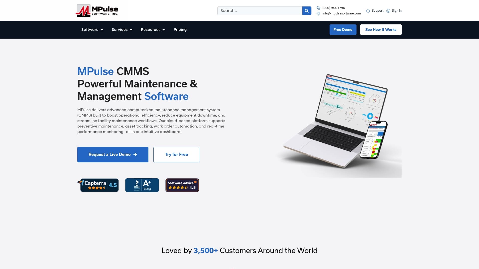
A checklist on paper can be easy to overlook, but using asset lifecycle management software helps track devices and costs efficiently. In a CMMS, it becomes the default way work gets done. Here is what we built MPulse CMMS to support:
- Tools to support maintenance recordkeeping
- Support for organizing maintenance records
- Calendar scheduling that keeps verification and follow-up work visible
- IIoT and real-time monitoring to capture the trigger evidence behind a failure
- Integration adapters that can reduce the need for manual re-entry
These controls make “update after verification” a routine step instead of a good intention. If you want help setting up coding governance, our implementation services team can work with you, and our preventive maintenance features are a practical place to start.
FAQ
How do you identify failure modes?
Start with the required function, then write down the observable deviation before assigning a cause. ISO 14224 examples include fail to start on demand, leakage, vibration, noise and overheating. These are observations, not diagnoses.
What is an acceptable failure rate?
There is no universal answer. A meaningful rate needs a defined population, operating exposure, failure definition and time basis. Benchmark by failures per operating hour, demand or cycle, segmented by asset class, duty and environment, as NERC guidance demonstrates.
What do failure analysis engineers do?
They verify the failure, determine its mode, diagnose the physical mechanism, test to reproduce it when needed, and recommend corrective action. ASM’s failure analysis guide describes this as a scientific method of defining the issue, proposing a hypothesis, gathering data and testing it.
What is FMEA in engineering?
FMEA is a systematic evaluation of how an item or process might fail, the effects of each failure mode and potentially its causes. Teams use it prospectively, then check it against coded work-order history to see which failures actually occur.
Sources
- Knowledge
- ISO 14224:2016 – Petroleum, petrochemical and natural gas industries — Collection and exchange of reliability and maintenance data for equipment